Finite element analysis, computational fluid dynamics, and multibody dynamics are among the most common simulation techniques.

Simulation techniques apply one or more discretization methods to solve physics problems. Engineers select a technique depending on the problem they need to solve or the properties they need to analyze. For example, finite element analysis (FEA) is typically used for structural, modal and thermal analyses, while computational fluid dynamics (CFD) is reserved for fluid flow problems.
Though many software platforms use a single technique to solve specific problems, multiphysics simulation software leverages several techniques to solve multiple problems simultaneously. Multiphysics software also considers the interactions of various physical phenomena and how such interactions affect system, structure or component performance. Though this article discusses FEA, CFD and multibody dynamics (MBD) techniques separately, multiphysics software tools often combine all these techniques into one platform.
FEA is a computational technique to analyze the behavior of complex structures and components under defined conditions. Though the terms FEA and FEM (finite element method) are often used interchangeably, FEM refers to the discretization method, and FEA refers to the analysis technique that uses FEM.
FEA simulation is widely used across industries for different applications, including:
- Static and dynamic structural analysis: Assessing the strength and durability of structures or components under steady-state and changing conditions.
- Modal analysis: Understanding the natural vibration characteristics of structures or components and predicting their performance under various conditions.
- Thermal analysis: Studying heat distribution and thermal stresses in components.
- Fluid dynamics: Simulating fluid flow and its interaction with structures (often combined with CFD).
- Electromagnetic analysis: Investigating electromagnetic fields in electrical devices.
- Biomechanics: Understanding the behavior of biological tissues for designing medical implants.
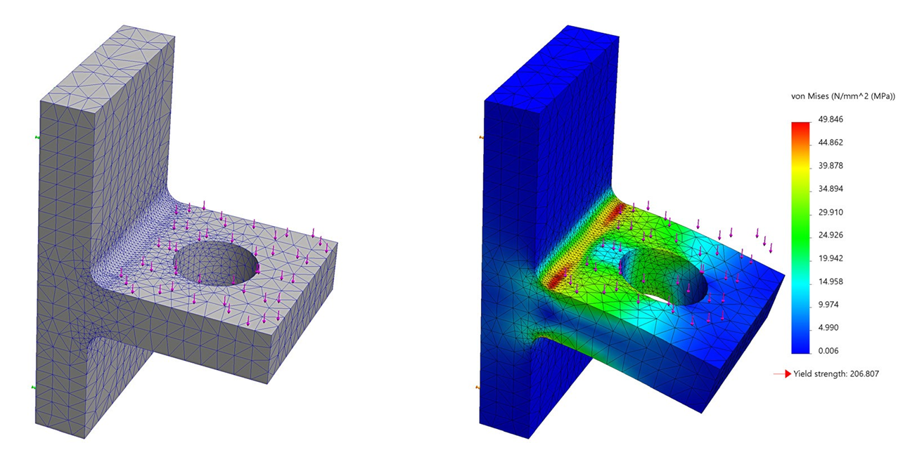
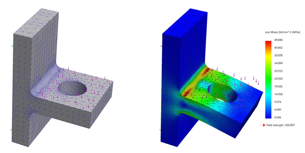
During FEA pre-processing, engineers divide a model into a finite number of smaller elements to form a mesh. They select different types of elements, including 1D, 2D or 3D elements, based on the model’s geometry and nature of the problem. For example, aerospace engineers may use 1D elements for fuselage frames, 2D elements for the aircraft’s skin (outer surface) and 3D elements, often tet or hex elements, for the landing gear.

Then, engineers specify the material properties for each material used in the model. These properties include Young’s modulus and Poisson’s ratio, which define how a material deforms under stress. Engineers also define boundary conditions, including constraints and loads applied to the model. The FEA software uses the material properties and boundary conditions to construct mathematical matrices for each element. It then solves the system of equations, thereby predicting the material’s response to applied loads.
During post-processing, engineers analyze the results, such as displacement fields, stress distributions and potential failure points, to assess the performance and safety of the design.
CFD is a simulation technique widely used to analyze the behavior of fluids (liquids and gases) and their interactions with surfaces. The fundamental equations governing fluid flow are the Navier-Stokes equations, derived from the conservation laws of mass, momentum and energy. CFD solvers often use the finite volume method (FVM) to discretize these equations, but the finite difference method (FDM) is sometimes used for simpler problems. FEM can also be used but is computationally expensive since CFD problems tend to require a large number of elements.
CFD simulation software analyzes fluid flows that are external or internal to a model. External CFD models are frequently used to supplement, inform or replace physical wind tunnel and aerodynamic testing in the aerospace and automotive sectors.
Internal CFD simulations are also used in such industries to help design and optimize the fuel flows, exhaust fumes or internal combustions associated with a vehicle’s engine. CFD simulations can also model mixing, heat transfer, chemical reactions and other phenomena that include the flow of gases or liquids.
Engineers start by inputting test geometry from CAD to CFD or multiphysics software. Tools within the simulation software, or third-party options, pre-process the geometry by filling in unintended gaps and simplifying complex shapes that will increase computations without affecting results. Then, engineers select whether a flow field is internal or external to the geometry. When choosing an external flow field, engineers must also denote how far the fluid flow will be calculated from the input geometry. They then input initial conditions, flow models and materials properties.
Engineers using CFD simulations must pay close attention to the flow models selected, particularly when dealing with turbulent flows. Chaotic, stochastic changes in pressure and flow velocity characterize turbulent flows. Several classes of models are used to simulate turbulence, such as direct numerical simulation (DNS), large eddy simulation (LES) and Reynolds-average Navier-Stokes (RANS) models. Different turbulence models may better suit certain applications, geometries, fluids, flow volumes, scales and internal or external flow fields.
Next, the geometry is typically meshed into smaller discrete cells to break the problem into smaller parts, making it easier to assign and solve the governing equations. These inputs are then passed onto a CFD solver to iterate the computations until their results converge to an answer. Tools within the simulation software, or external third-party options, are then used to post-process the results into flow diagrams, charts, geometries and reports.
In the CAE simulation world, MBD refers to multibody dynamics, not model-based definition, model-based design or model-based development. Model-based definition is a feature in various CAD, PDM and PLM software that enables users to annotate and associate part information with a 3D model, making it a single source of truth for that part. Model-based design or development has roots in systems design and process control and involves producing a complex system model using flow charts, mathematical equations and simple simulations.
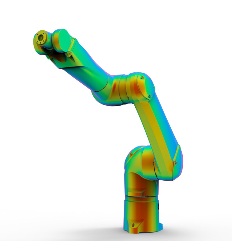
MBD simulations assess mechanical systems made up of rigid or elastic parts. Using equations of motion, the software numerically assesses the kinematics of each part in the system based on its mass, center of mass, inertia and properties after applying internal and external forces or torques. The motions that MBD simulations might describe include the translational and rotational movements of aircraft parts, construction equipment, robots, vehicles or any other system with moving parts. Some assessments engineers can perform using MBD include the study of noise, vibration and harshness (NVH), vehicle performance, electronic control systems and more.

Much like model-based design and model-based definition, MBD simulation is often used early in the product development cycle to virtually test the performance of a design before any physical assets are produced.
MBD simulations can also be used in digital twins to monitor and assess real-world assets. However, unlike model-based design digital twins, which traditionally assess industrial systems, MBD digital twins assess real-world system motion.


