
Balancing manufacturing precision and cost by allowing as much variation as possible while ensuring performance can turn variability into an advantage.
The development of software tools to help engineers design new products and optimize their production has taken a significant step forward with capabilities to simulate and analyze the changes in GD&T symbology and tolerances and get that information into the product’s digital thread.
The ideal digital thread connects, in a complete, transparent, and seamless flow, all data and information from any relevant domain (e.g., engineering, manufacturing, quality, service) or solution (PLM, CAD, ALM, SLM, and so on) that defines a product. The digital thread enables efficient collaboration and decision-making throughout the product lifecycle.
As defined by CIMdata, the digital thread is “a communication framework that connects data flows, which can be used to produce an integrated and holistic view of an asset’s data from physical and virtual systems (i.e., its digital twin) throughout its lifecycle across traditionally siloed functional perspectives.” Also connected to the product’s or system’s digital thread are the bills of materials (BOMs) for engineering, manufacturing, and service.
That’s the ideal—everything in the lifecycle connected end-to-end—but everyday reality falls short. Digital threads offer huge benefits but often have breaks; accumulating those connections and related benefits is a never-ending journey. The practical approach is to implement subsets of digital threads based on business benefits; eventually, unbroken connectivity is achieved.
The digital thread can connect many types of simulation, the best known being finite element analysis (FEA) and computational fluid dynamics (CFD). The simulation market is diverse, and many specialized solutions are used for specific products and applications. Companies also create proprietary solutions when they believe it will give them a competitive advantage.
Beyond physics-based solutions, model-based systems engineering (MBSE) is a sophisticated approach to simulating overall product performance by managing requirements, functional design elements, logical design elements, and the physical product definition (i.e., usually an engineering bill of materials or BOM or structure). This approach is also called Requirements Functional Logical Physical (RFLP).
Variation is typically specified by engineering using tolerances on dimensions, GD&T symbology, and with textural notes for manufacturing planning and quality. Every manufacturing process has variation, some more than others. Because precision adds costs in manufacturing, engineers want to allow as much variation as possible in parts and assemblies while still meeting part interchangeability and performance requirements. In general, more allowable variation lowers manufacturing costs. Engineers and managers work endlessly to account for variability and reduce its negative impact on cost and product performance. In the best cases, they leverage variation to optimize product cost.
Historically, variation specifications were captured on 2D drawings generated “downstream” from 3D models as drafting objects. These specifications drive downstream processes such as product performance analysis, manufacturing planning, CNC programming, and inspection. Engineers should assign variation—tolerances, including dimensional, GD&T, and manufacturing notes during design when they are thinking about how the product functions. But ordinarily, variation is assigned after the 3D modeling is done and in graphical form (rather than as numeric data) which is hard for other software to consume. As a serial process, the design release timeline is extended, and downstream applications such as manufacturing planning cannot start until drawings are released.
GD&T—geometric dimensioning and tolerancing—the best-in-class way to specify variation, is a complex language. GD&T requires syntax and application validation to ensure it is correctly applied. When this is done as a manual checking function, it happens late in the development cycle, when changes are usually the costliest. (Tools exist within CAD solutions, either natively or from third parties, to validate GD&T by ensuring the syntax is correct, reducing the need for manual validation.)
In recent decades, CAD solution providers have moved beyond drafting-oriented GD&T by using Product Manufacturing Information (PMI), which enables variation specifications to be associated directly with the 3D model. A 3D model with PMI is the sum total of data and information manufacturing needs to realize a product: geometry, dimensions and tolerances, Q/A and Q/C datum points, material specifications, surface finishes, annotations for manufacturing, production planning in CAM, and so on.
PMI data can be consumed by downstream applications associatively within the digital thread, reducing transcription errors and enabling shorter, more accurate change cycles downstream.
Historically, variation analysis, including stack-ups, has been done manually or in disconnected spreadsheets. More recently, stack-up and other analysis tools read PMI data to analyze variations and their impact on tolerances or to specify processes directly linked to 3D CAD models. As designs change, analyses becomes easy since it is incorporated directly within the digital thread, enabling variation simulation to keep up with changes, improving the assessment of the impacts of downstream changes in process planning for manufacturing, the accuracy of cost planning, and the predictability of product performance.
Poor change impact analysis can lead to rework, shipping delays, and product recalls. Modern analyses that use PMI reduce these risks.
Tolerance stack simulation—connecting the threads
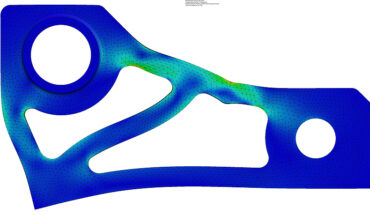
One of PMI’s benefits is that it enables the building of 2D and 3D tolerance models. These models predict the variation of parts based on tolerance values and GD&T callouts and can predict assembly variation, supporting manufacturing and product performance. For example, tolerances on hole patterns in mating parts, such as a purchased motor and a fabricated mounting bracket, can be used to determine whether parts will fit all the potential tolerance values.
The latest software tools will suggest component tolerances to manage assembly variation to lower costs and improve product performance. Tolerances that have a significant impact are reduced, and tolerances that do not are relaxed. This optimizes product cost since less precise processes can be used on non-critical dimensions and features.
Reliable data linking requires a PLM solution that manages data configuration and related processes. Once PMI is encoded in CAD data, it can be consumed by native downstream applications such as CAM or third-party applications that use the CAD API or via the STEP protocol. When changes happen, downstream files are flagged as impacting the PLM solution and can be reviewed and updated as needed.
Incorporating variation simulation within the digital thread enriches product information and makes it easier to access and use for impact analysis and traceability inquiries. Better variation management improves cost, quality, and time-to-market.
Integrating variation analysis and the digital thread drives many business benefits:
- Finding issues and problems earlier to improve quality.
- Facilitating Shift Left initiatives for completing engineering tasks, analyzing choices, and reaching decisions as soon as possible, shortening time-to-market.
- Making data more consistent and processes more repeatable.
- Upskilling the engineering workforce with better knowledge capture to offset the retirements of experts and the difficulty of replacing them.
- Raising confidence in a product’s design before capital is committed to it.
With all this in mind, it’s optimal to implement the digital thread in subsets keyed to expectable business benefits. Variation analysis is a powerful capability that increases in value when incorporated into the digital thread.
Tom Gill, Principal Consultant & Practice Manager for PLM Enterprise Value and Integration CIMdata Inc.


