How modeling material behavior and simulating additive manufacturing processes can help engineers ensure success with 3D printing.
Any engineer worth their salt understands the value of simulation. The ability to model the physics involved in a new process or design accurately is something engineers who lived before the advent of computer-aided engineering (CAE) could only dream of.
In the context of additive manufacturing (AM), simulation can be used to predict thermal and mechanical phenomena of the 3D printing process itself, helping engineers optimize both 3D printing time and material usage. By leveraging simulation in these ways, engineers can gain critical insights into part performance before fabrication begins.
How does mechanical simulation apply to additive manufacturing?
Compared with subtractive manufacturing processes, such as milling or turning, additive manufacturing introduces several novel challenges to part designs. These include residual stresses and anisotropy resulting from the cooling of AM parts, as well as stress concentrations in consolidated or lightweight designs.
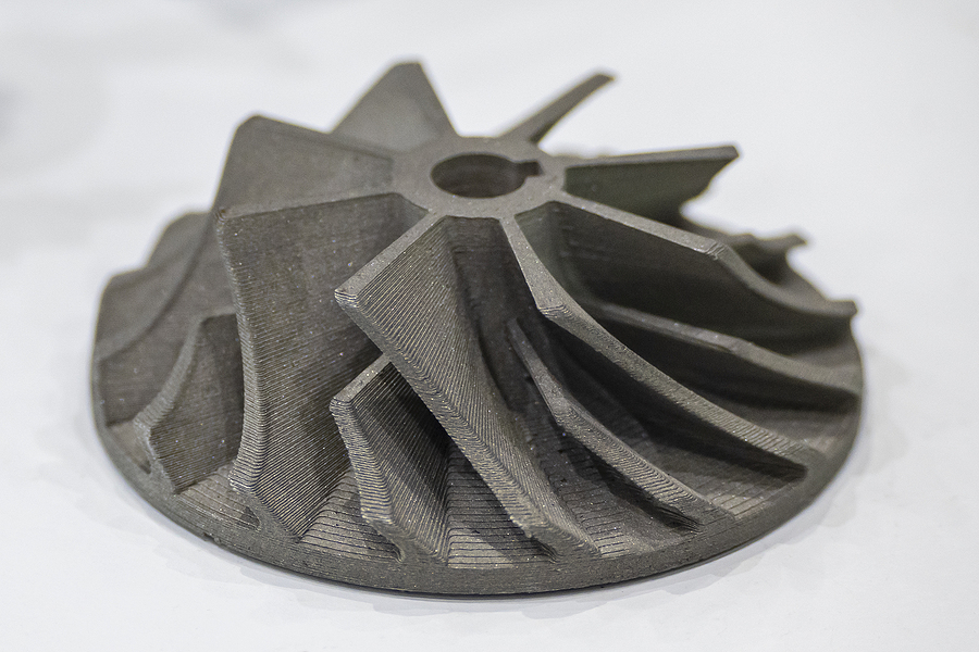
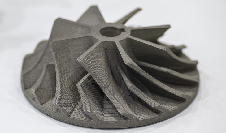
This is why applying a variety of simulation and modeling techniques is particularly crucial in AM applications. Static analysis can predict deformations due to warping in thin-walled parts or the distortions that often crop up in impeller blades, while dynamic analysis can help identify the effects of vibrations and other variable forces on a 3D printed part. Fatigue and durability analysis helps forecast part lifespans under cyclic loads, which is particularly important for functional components.
The techniques employed to these ends include finite element analysis (FEA), a cornerstone of mechanical simulation, with the finite element method (FEM) modeling mechanical constraints both at the part scale and in the macro-dynamics of entire assemblies. Ideally, engineers can use simulations to “pre-deform” their parts, ensuring that target net shapes are achieved and minimizing trial-and-error iterations as well as the need for excessive post-processing.
How does process simulation predict the mechanics of 3D printed parts?
Because of the unique, multi-physics nature of many additive manufacturing processes, utilizing process simulation can help engineers understand how the AM build parameters will influence part geometries. Examples include:
- Using thermal histories to predict how heat input and dissipation during the printing process will affect grain structures and residual stress in metal AM
- Identifying regions prone to voids or porosities that could compromise mechanical strength
- Optimizing process parameters to reduce warping, particularly for especially complex geometries
By drawing on multiscale modeling at the microscopic, mesoscopic and macroscopic levels, engineers can gain a greater understanding of the connections between thermal and mechanical behavior, ultimately building up a comprehensive picture of how process changes impact the final mechanical properties of the 3D printed part.
How does thermal simulation help predict mechanical properties in AM parts?
As indicated above, a 3D printed part’s thermal history has a direct bearing on its microstructure, which in turn determines its mechanical properties. In the context of metal AM, for example, rapid cooling can create directional grain growth, resulting in anisotropic properties, whereas slower cooling can increase ductility at the cost of strength. For polymer AM, cooling rates directly affect crystallinity, which in turn affects part stiffness and tensile strength.
The challenge in this case is the diversity of timescales involved in the 3D printing process, from nanoseconds within the melt pool dynamics to hours when it comes to complete build cycles. This is one reason that engineering researchers are exploring reduced-order models (ROMs) and hybrid approaches to find a balance between fidelity and computational efficiency.


